|
|
|
The appropriate geometrical arrangement of obstacles (noise protection walls, barriers, buildings etc.) can effectively reduce the influence of a sound source on a place of immission. Similar to the shadow of light, an acoustic shadow is formed behind an obstacle but is reduced by sound diffraction at the edges. As mentioned in section 2.5 (The effect of noise protection constructions), the following indications and annotations for the construction and structuring of barriers can be derived:
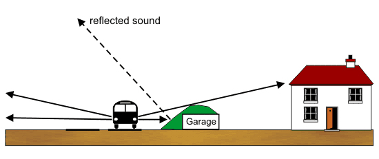
Noise protection barriers In city planning, noise protection barriers (as in fig. 7/8) are frequently used as noise protection features, especially for noise abatement at roads. Adequately shaped barriers can be easily integrated into the surroundings, they can be planted and the required masses of earth often arise from the anyway existing earth that is excavated during the digging of a road or a building area. As a consequence, they are often less expensive than noise protection walls. What is more, barriers do not reflect sound. The area averted from the noise source can be used e.g. for playgrounds and chutes for children, pavements, bike paths and garages. The sketch in figure 7/9 shows an example of how noise protection walls can be realized (with an integrated row of garages). One disadvantage of noise protection barriers is their relatively large space requirement, which is often not available in already developed areas. In the case of newly planned projects, it is both possible and necessary to secure the space required for noise protection features in the legally binding land-use plan (§ 9 para. 1 no. 24 of the Federal Building Code) even if a road for example shall only be built later. Another disadvantage is the reduced efficiency of such barriers compared to noise walls as the upper edge of the barriers is farther away from the sound source (due to the angle of repose) and bigger heights are therefore generally necessary. The solution could be a combination of wall and barrier or steeper retaining barriers, which can be planted. As for the overall appearance of the landscape, noise protection barriers are mostly preferred to noise protection walls. Individual walls and barriers can disturb the discharge of cold air near the ground (Climate Booklet for Urban Development, 2012). In this case, other solutions should be found (e.g. cuts or a tunnel). The use of both noise barriers and noise protection walls is restricted within towns or cities due to structural limits. The conflict must be weighed in the context of urban planning.
Noise protection walls Noise protection walls (as in fig. 7/10) are an efficient noise abatement measure. Many years of experience have led to a huge number of optically appealing barrier systems, which also withstand weather conditions. The advantage of walls compared to noise barriers is their significantly lower space requirement, and this is why they are often the only possible shielding measure in already developed areas. They can be better integrated into the landscape by using adequate materials and by planting them with climbers. But it is more difficult to integrate them harmoniously into the cityscape than barriers. Noise walls are rarely installed within towns or cities as they optically disturb and divide the urban landscape and cut down important lines of sight, which are essential for all traffic participants. And they form an obstacle for pedestrians and cyclists as they restrict the crossing possibilities. Figures 7/11 to 7/13 give examples of how to use noise protection walls. As a wall can be established relatively close to the noise source, its height is mostly lower than the height of an equivalent barrier. Along railway routes, even relatively low walls (with a height of about 70 cm) close to the tracks achieve an efficient noise reduction of up to 6 dB(A) as one of the main noise sources of rail traffic (i.e. wheel/track noises) is shielded here. They have the advantage that they are visually less disturbing. However, special security and maintenance aspects need to be considered; railroad works are significantly complicated for example. This is why such walls are generally no option with more than two tracks. The Orientation drawings for noise barriers outside civil engineering works (Richtzeichnungen für Lärmschirme außerhalb von Kunstbauten/ RiZaK-88) contain schematic diagrams and indications for the planning and installation of noise barriers. The technical structuring of noise barriers is laid down in the Additional technical regulations and directives for the installation of noise protection walls at roads (Zusätzliche technische Vorschriften und Richtlinien für die Ausführung von Lärmschutzwänden an Straßen/ZTV-Lsw 06, version of 2006). This directive issued by the Federal Transport Minister specifies the requirements on the material, stability, persistence and sound absorption of noise protection walls. It also defines inspection procedures, allocation, approval and warranty. What has to be considered when noise protection walls are installed is the reflection of sound. Otherwise the walls can cause an increase of the noise level by up to 3 dB(A) for residents living opposite of them, and this corresponds to a doubling of the traffic volume. Figures 7/15 and 7/16 give examples of this problem. So we can see that it is important to verify in every single case whether the installation of a sound-absorbing wall is necessary or not. Noise protection walls should be sound-absorbing in order to minimize
The absorption characteristics of noise protection walls and sound-absorbing wall coverings are determined according to DIN EN ISO 354. We speak of highly absorbing noise walls if the reflected acoustic beam is by 8 dB lower than the beam hitting the wall.
Steep walls A special form of noise protection features are steep walls (fig. 7/17 and 7/18), which is something between a noise barrier and a noise protection wall. A steep wall has the form of an unequal trapeze, which can even reach the shape of an almost rectangular trapeze in some cases. The use of artificial supporting structures, which is required here, allows for a significantly steeper inclination of the trapeze's sides than the usual slope inclination determined by the shear strength of the integrated soil. The use of e.g. gabions (wire baskets filled with stones) as supporting elements in the lower part of the wall allows for the construction of bigger heights. Often only one side of a steep wall is actually steep; the other side has the usual slope of 45 to 60 degrees depending on the ground. Steep walls can be used if
Effective noise protection can be achieved by directing roads through cuts or troughs (fig. 7/19 to 7/21). The required shielding effect results from the slope, which should be as steep as possible in order to offer optimum protection. If retaining walls are used, it might be necessary to install a sound-absorbing covering to make sure that the sound insulation is not impaired through reflections (see above). The effect of cuts can be intensified by using additional (and mostly low) noise protection walls.
Raised transport routes Raised transport routes (roads, tracks), e.g. on embankments, have the advantage that the abutments along the route can also function as noise barriers (fig. 7/22 and 7/23). Additional noise protection walls can substantially intensify the shielding effect in individual cases. Three or four-storey development for example can be protected through a raised road in an altitude of 6 m with low noise protection walls.
Development as noise abatement measure An interesting noise protection measure for city planning are long buildings which are insensitive to noise. These are closed buildings whose rooms facing the road
The orientation of a building towards the road is also of significance here. A road passing a residential area in the north is much less harmful than one in the south as habitable rooms are mostly directed to the south. Seamless building blocks of an appropriate length and height or perimeter development can reduce the noise level by up to 25 or 30 dB(A). What is essential in this context is to prevent noise gaps. This measure is particularly interesting in the context of town renewal and restructuring works in heavily noise-polluted inner city districts. Access roads or passage ways between the buildings can nevertheless be realized if their width is low compared to the depth of the building. But the achievable sound level reduction can possibly be lower then. Cut-and-cover methods like detached or semi-detached houses or groups of adjoining houses do not prevent the propagation of sound through the gaps with the result that there are no quiet zones behind the buildings. Such gaps can be partly closed by garages. Figures 7/24 to 7/26 give examples of noise abatement through buildings.
Partial and total enclosure, tunnels An enclosure is a capping body over a deep-set transport route (lying in a cut), which reduces the sound from the transport route in combination with a slope or retaining wall on at least one side of the cut. An overhead noise barrier is a long hall-like construction over a transport route, which prevents a direct propagation of the sound. Figure 7/27 gives some examples of already realized or proposed enclosures, overhead noise barriers and tunnels. Tunnels are optimum noise abatement features as the noise from roads or tracks is completely dammed in the protected area. Furthermore, tunnels protect from exhaust gases. Problems caused by exhaust gases and noise can reoccur, however, at the tunnel portals provided that there are sensitive uses. This is why tunnels must be long enough to effectively protect an area. The construction of tunnels is very expensive and they also require costs of operation (lighting, ventilation, fire protection, cleaning). On the other hand, the space above or beside a tunnel can be additionally used at higher quality for city planning purposes – an aspect which must not be neglected considering that building plots in cities are very rare and expensive. A special case of a noise protection tunnel is the lightweight construction with an acoustic ceiling by Züblin. It has continuous openings above the roadsides and thus allows for natural ventilation and lighting (fig. 7/28) Acoustic measurements gave noise reductions at ground level of about 20 dB(A) (at a distance of 10 m to 20 m from the tunnel).
Vegetation The sound-absorbing characteristics of vegetation are traditionally overestimated. Vegetation as a noise protection measure in city planning is practically out of question as only a strip of thick woodland with a width of at least 100 m and thick undergrowth reduces the sound level by 5 to 10 dB. Single trees or bushes offer practically no noise protection. Table 7/2 shows the reduction of the continuous sound level at a road through homogeneous vegetation in protection zones.
Table 7/2: Noise reduction through vegetation What must not be underestimated, however, is the visual shielding effect of vegetation and the resulting positive psychological implications for the affected people (fig. 7/29). So we can certainly say: What the eye does not see, the ear does not hear consciously! Trees planted at the side of a road as a structural design element can revaluate the road space and reduce the disturbance effect of noise for both residents and pedestrians.
The orientation of the buildings as well as a flat's or house's floor plan also allow for a reduction of the noise level (fig. 7/28). Rooms with a less noise-sensitive use, like kitchens, bathrooms and staircases, can look onto the road while rooms with noise-sensitive uses, like living rooms or bedrooms, are situated on that side of the building which is averted from the road. The noise level on the averted side is reduced by about 15 dB in the case of closed development and by about 5 dB in the case of dispersed development. The necessary designations can be fixed in the legally binding land-use plan for a binding determination of such a land-use allocation. If all active noise abatement measures are exploited or if they are impossible (in inner city districts or in already built-up areas), only constructional noise abatement measures beyond the standard measure at the building itself remain. The requirements for constructional noise abatement measures can be deduced from DIN 4109 Section 5 (Sound insulation in buildings) concerning the reduction of exterior noise. The basis for the designation of the required sound insulation of exterior building components against exterior noise are different sound level ranges, to which the existing or expected "relevant exterior noise levels" are assigned. Table 7/3 gives the requirements for the sound insulation of exterior building components, separated according to sound level ranges and room uses.
Table 7/3: Requirements for the sound insulation of exterior building components pursuant to DIN 4109 The simplified procedure deduced from DIN 18005 Part 1 (see also section 3.1.2.1) for typical road traffic situations can be used for example for estimating the "relevant exterior noise level" in front of facades. We would also like to recommend the browser-based decibel calculator available in the online version of the Noise Manual. As the walls of houses generally possess a high sound insulation value (except for some old buildings), additional noise abatement features are usually only required at windows and roller shutter boxes. At attic flats, the insulation of the roof can be helpful. The quality of soundproof windows must correspond to the existing exterior noise level and the desired indoor level. In the context of legally binding land-use plan designations (§ 9 para. 1 no. 1 of the Federal Building Code), which provide for sound insulation measures according to DIN 4109, the "relevant exterior noise level" mentioned therein only refers to the daylight rating level. Along heavily frequented roads and especially railway routes, however, the sound levels during the night are nearly as high as during the day. So a sound level difference between day and night of 10 dB(A) as implied in DIN 4109 is no longer given. In these cases, the recommendations by the Bavarian State Agency for Environmental Protection shall be taken into account (The required sound insulation value of soundproof windows – a comparison of different regulations, 2007). Details on the sound insulation of windows are given in VDI guideline 2719. This guideline also contains reference values for indoor noise levels (for incoming exterior sound), which are outlined in a simplified way in the following table 7/4.
Table 7/4: Reference values for indoor noise levels pursuant to VDI 2719 VDI guideline 2719 divides windows into sound insulation classes from 0 to 6. Class 0 (leaky windows with single glazing) has an assessed sound insulation value of < 24 dB while windows of sound insulation class 6 (double windows with separate frames, special gaskets, very big pane distances and glazing with thick glass) have a sound insulation value of > 50 dB (see table 7/5).
Table 7/5: Sound insulation classes for windows pursuant to VDI 2719
|
|
|||||||||||||||||||||||||||||||||||||||||||||||||||||||||||||||||||||||||||||||||||||||||||||||||||||||||||||||||||||||||||||||||||||||||||||||||||||||||||||||||||||||||||||||||||||||||||||||||||||||||||||||||


 7.1.6 Noise barriers